
JSC "STCD"
Diagnostics CenterURL: https://diaprom.ru/
E-mail:
Address: office 329, Gazgoldernaya st. 14, Moscow 109518
Telephone/Fax: (495) 690-9195
E-mail:
Address: office 329, Gazgoldernaya st. 14, Moscow 109518
Telephone/Fax: (495) 690-9195
Pipeline displacement monitoring systemExperience of Implementation of Software-Hardware Suite of Pipeline Displacement Monitoring System
1. PurposeThe pipeline displacement monitoring system is intended for periodic monitoring in the normal operation modes of the thermal displacements of the following pipelines:
The pipeline displacement monitoring system belongs to normal operation systems, the components of the system belong to safety class 4 according to General safety regulations OPB 88/97. The components of the system and the system as a whole as well as the organization of installation, maintenance and operation activities in terms of general requirements and electrical safety requirements comply with the requirements of GOST 12.1.004-85, GOST 12.1.019-79 and GOST 12.1.030-81. The pipeline displacement monitoring system belongs to continuous use systems. The monitoring of pipeline displacement is performed automatically in the modes of the reactor system normal operations and abnormal conditions. 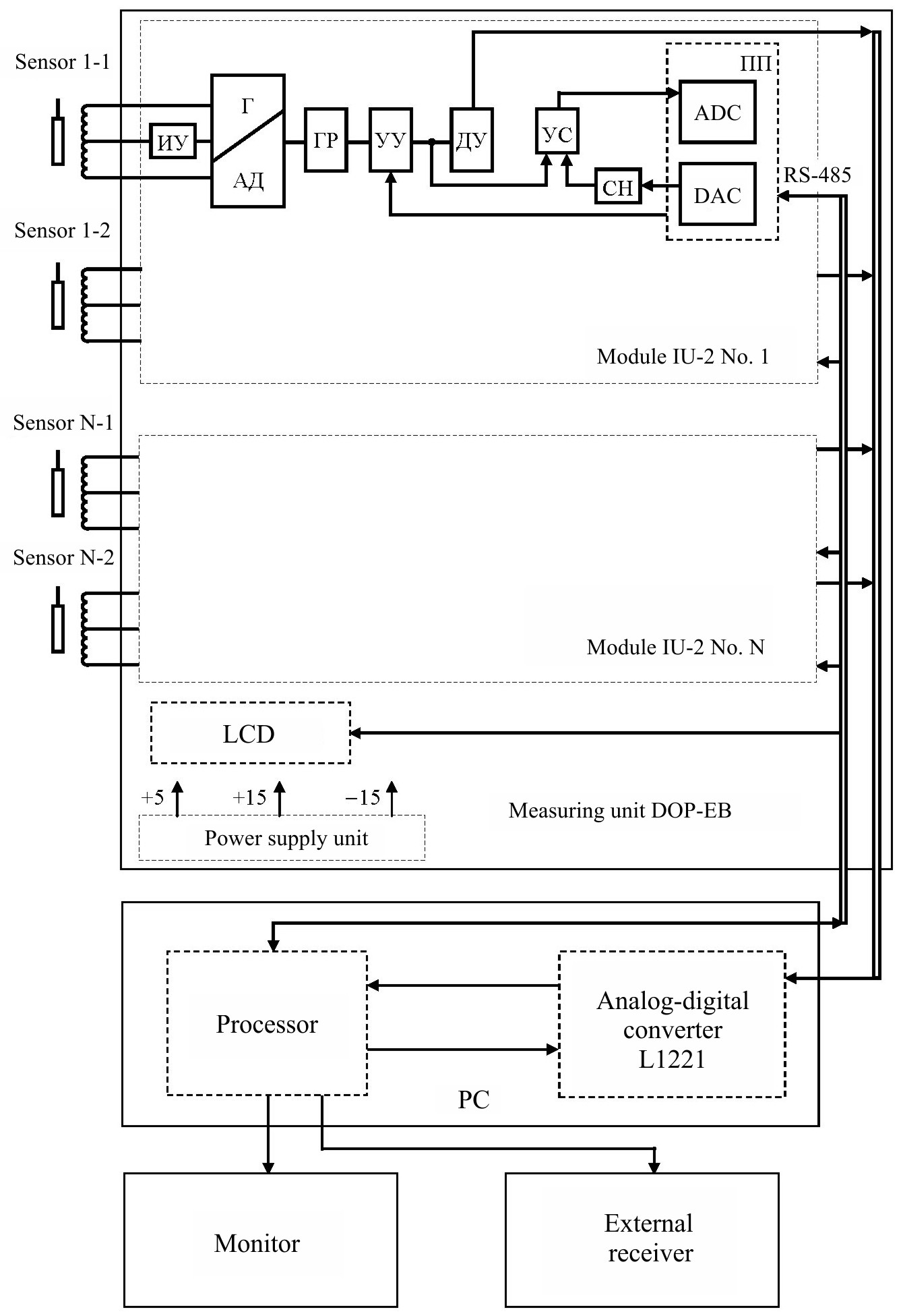 Figure 1 – Electrical Diagram of Pipeline Displacement Figure 1 – Electrical Diagram of Pipeline DisplacementMonitoring System The following activities are performed in the on-line mode:
Processing and analysis of the displacements of monitored pipelines on the basis of measurement results are performed on-line. The purpose of the analysis is to evaluate the condition of steam generator supports and pipelines by way of comparison of the measured displacement values with the estimated (design) values, logging of the analysis results and display of generalized diagnostic data on the anomalies on the monitor or remote data terminal. The pipeline displacement monitoring system is an information system. The system does not provide control actions to the reactor protection systems. The pipeline displacement monitoring system complies with the requirements of «Special conditions of supply of equipment, instruments, materials to nuclear facilities. The software-hardware suite of the pipeline displacement monitoring system ensures self-check of its software and hardware. 2. Pipeline displacement monitoring system structureThe pipeline displacement monitoring system is an off-line information system comprising relative displacement monitoring channels and software-hardware suite (UII). In order to monitor thermal displacements the pipeline displacement monitoring system uses:
The use of relative displacement inductive sensors to monitor thermal displacements is preconditioned by the simplicity of their manufacture and adjustment and operational reliability. Similar engineering solutions are used to monitor the displacements of WWER-1000 reactor system equipment at Kalinin NPP Unit 3, "Tianwan" NPP, etc. The specialty of the above channels consists in the possibility of remote calibration and balancing. A half-bridge circuit is used for the relative displacement sensor configuration. The relative displacement sensor DOP-04 measures pipeline displacements with reference to building structures in the quasi-static mode (slow thermal displacements in various RS operation modes). Displacements are monitored within the range ±50 mm. The pipeline displacement monitoring system includes (in a delivery set per a NPP Unit):
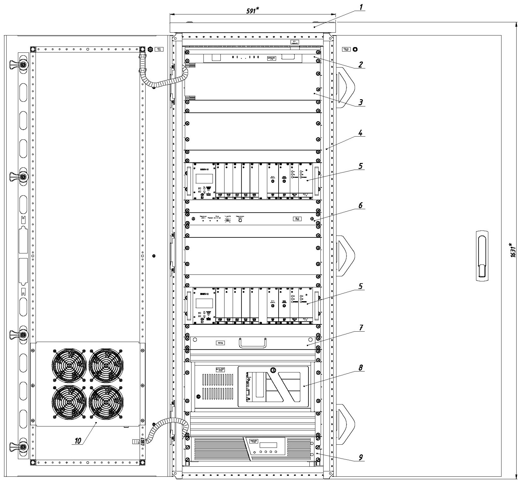
1 – ventilation device UV-1; Pipeline Displacement Monitoring System Data-measuring device UII (see Figure 2) contains unified basic software-hardware facilities that include:
Attachment points ensure secure sensor fastening upon the monitored equipment. Terminal boxes enable reducing the cable communication lines number. The block-diagram of the pipeline displacement monitoring system is given in Figure 1. The digital information exchange between the pipeline displacement monitoring system and the IT system is performed over Ethernet interface using network boards included in the pipeline displacement monitoring system. The link of the pipeline displacement monitoring system with the IT system is required to receive the values of process parameters used during the system operation. 3. Operation of Pipeline Displacement Monitoring SystemDuring the thermal displacement monitoring the pipeline displacement monitoring system ensures simultaneous recording of 20 analogue signals from relative displacement sensors. The polling period of relative displacement sensor measuring channels during the thermal displacement measurement is 5...20 sec. and is set by the user in the software settings. The signals form the relative displacement sensors DOP-04 arrive in the vibration and displacement monitoring unit BKVP-12 with the installed measuring modules IU-2P, where they are demodulated and converted into a voltage signal ±6.3 V, proportional to mechanical displacements of equipment and analog signals are transmitted to the inputs of ADCs installed in the basic system unit BSB-02R. The functional test of relative displacement sensor channels is initiated by the operator’s commands made from BSB-02R (main computer) included in the data-measuring device UII and is displayed on the embedded system monitor screen. BSB-02R records multichannel time realizations of sensor signals. The input data is exposed during measurements to simultaneous multichannel analog-to-digital conversion that results in the generation of signal time realizations. Digitized signal values are stored in the system data base and are used for further processing (comparison with the estimated values) as well as for the long-term storage of measurement data in the system archive. When estimated and actual displacement values are compared, diagnostic data are generated to be displayed on the monitor (remote data terminal) and stored in the diagnostic data base. The functions of the pipeline displacement monitoring system are subdivided into informational and general. The information functions are:
The general functions of the pipeline displacement monitoring systems are:
|
| © 2003-2024 JSC "STCD" E-mail: Telephone/Fax: (495) 690-9195 |
About Us | Activities Integrated Management System | Feedback | Contacts |


|